
1. Ray Optics or Geometrical Optics In this optics, the light is considered as a ray which travels in a straight line. It states that for each and every object, there is an image.
2. Reflection Reflection is the phenomenon of changing the path of light without any change in the medium.
3. Reflection of Light The returning back of light in the same medium from which it has come after striking a surface is called reflection of light.
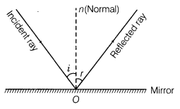
4. Laws of Reflection
Two laws of reflection are given as below:
(i) The angle of incidence i is equal to the angle of reflection r.
i.e. ∠i = ∠r.
(ii) The incident ray, reflected ray and normal to the reflecting surface at the point of incidence all lie in the same plane.
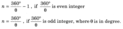
5. Total number of images formed by two plane mirrors inclined at an angle θ with each other is given by
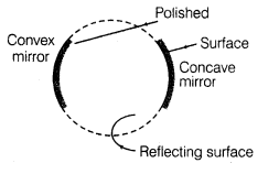
6. Reflecting surface of a spherical mirror is a part of a hollow sphere. Spherical mirrors are of two types, (i) Concave spherical mirror (ii) Convex spherical mirror.
7. Sign Convention All measurements should be taken from pole of mirror. All measurements along the direction of incident ray will be positive and opposite to incident ray are negative. All the measurements for the distances above the principal axis are taken as positive and below the principal axis are taken as negative.
8. For a real object, u is negative whereas v is negative for real image and positive for virtual image.
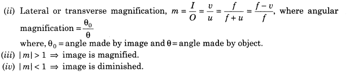
9. Mirror Formula Mirror formula is a relation between focal length of the mirror and distances of objects and image from the mirror.
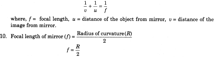
11. Linear Magnification The ratio of the size of the image formed by a spherical mirror I to the size of the object O is called the linear magnification produced by the spherical mirror.
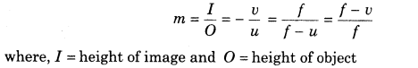
12. Magnification (m) It is negative corresponding to real image and positive for virtual image.
13. Refraction The phenomenon of changing in the path of light as it goes from one medium to another is called refraction.
14. Laws of Refraction
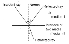
Two laws of refraction are given as below:
(i) The incident ray, refracted ray and the normal to the refracting surface at the point of incidence lie in the same plane.
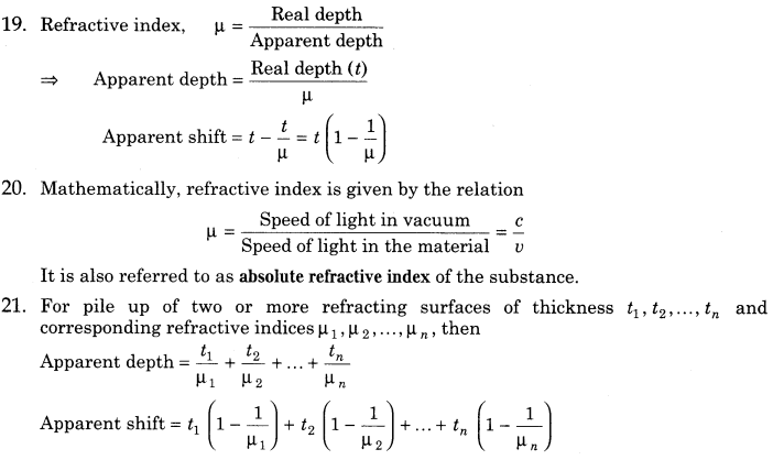
(ii) The ratio of the sine of the angle of incidence to the sine of the angle of refraction is constant for the two given media. This constant is denoted by n and is called the relative refractive index.
n = sin i/sin r (Snell’s law)
where, n is refractive index of the second medium when first medium is air.

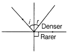
17. Total Internal Reflection (TIR) When a ray of light travelling from denser medium to rarer medium is incident at the interface of two medium at an angle greater than the critical angle for the two media, the ray is totally reflected back to denser medium. This phenomenon is called Total Internal Reflection. It occurs only when angle of incidence in denser medium is greater (not equal) than critical angle, i.e. i> ic.
18. Principle of reversibility of light states that when final path of a ray of light after any number of reflections and refractions is reversed, the ray retraces its entire path.
22. Optical fibre, mirage, sparkling of diamond, totally reflecting prism, etc. work on the principle of total internal reflection.
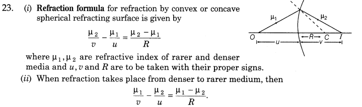
24. Lens is a transparent medium bounded by two surfaces of which one or both surfaces are spherical.
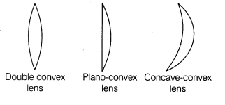
(i) Convex or Converging Lens A lens which is thicker at the centre and thinner at its end is called convex lens.
Convex lenses are of three types which are given as below:
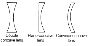
(ii) Concave or Diverging Lens A lens which is thinner at the centre and thicker at its ends is called a concave lens.
Concave lenses are of three types which are given as below:
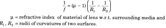
25. Lens maker’s formula
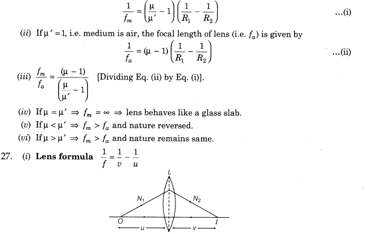
26. When lens of refractive index μ is immersed in a medium of refractive index μ, then
(i) When lens is taken in another medium, then focal length changes to fm which is given by
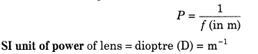
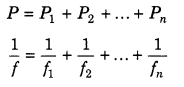
28. Power of Lens The ability of a lens to converge or diverge the rays of light incident on it is called the power of the lens.
29. Power of combination lenses in contact is given by
30. Magnification by combination of lenses
m = m1 × m2 × m3 ………..
31. (i) Prism have got the property of bending the incident light towards its base.
A prism is a portion of a transparent medium bounded by two plane faces inclined to each other at a suitable angle.
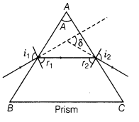
(ii) When the prism is adjusted at angle of minimum deviation, then
(a) angle of incidence is equal to the angle of emergence
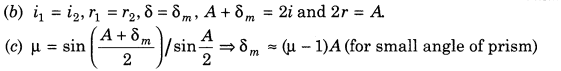
31. Dispersion by a Prism The phenomenon of splitting of light into its component colours is known as dispersion.
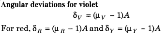
Angular Dispersion Angular dispersion produced by a prism for white light is the difference in the angles of deviation for two extreme colours i.e. violet and red.
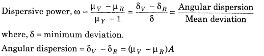
Dispersive Power Dispersive power of a prism is defined as the ratio of angular dispersion to the mean deviation produced by the prism.
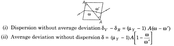
33. Combining two thin prisms we can study two conditions
1. Wave Optics Describes the connection between waves and rays of light. According to wave theory of light, light is a form of energy which travels through a medium in the form of transverse wave.
2. Wave front The locus of all those particles which are vibrating in the same phase at any instant is called wave front. Thus, wave front is a surface having same phase of vibrating particles at any instant at every point on it.
3. Phase Speed Phase speed is the speed with which wave front moves and it is equal to wave speed.
4. The shape of wavefront due to a
(i) point source is spherical
(ii) line source is cylindrical
(iii) source at infinity is a plane.
5. A line perpendicular to a wave front is called a ray. The direction of rays are always perpendicular to the wave front along the direction of propagation of wave.
6. Huygens’ Principle Huygens’ principle is essentially a geometrical construction, which gives the shape of the wave front at any time, allows us to determine the shape of the wave front at a later time. According to Huygens’ principle,
(i) Every point on a wave front behaves like a light source and emits secondary wavelets.
(ii) The secondary wavelets spread in all directions in space (vacuum) with the velocity of light.
(iii) The envelope of wave front of secondary wavelets, after a given time, along forward direction gives the new position of wave front.
7. The laws of reflection and refraction can be verified using Huygens’ wave theory.
8. Huygens’ wave theory successfully explains the phenomenon of interference, diffraction and polarisation.
9. As, frequency v is characteristic of the source, therefore v = 1/T remains the same as light travels from one medium to another.
10. Wavelength is inversely proportional to refractive index (μ) of the medium
i.e. λ’ = λ/μ
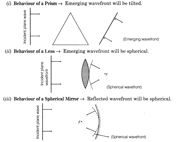
11. Behaviour of a Prism, Lens and Spherical Mirror towards Plane Wave front
12. Laws of reflection on the basis of Huygens’ wave theory As shown in figure, consider a plane wave front AB incident on the reflecting surface XY, both the wave front and the reflecting surface being perpendicular to the plane of paper.
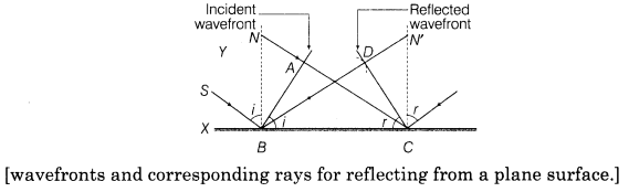
First the wave front touches the reflecting surface at B and then at the successive points towards C. In accordance with Huygens’ principle, from each point on BC, secondary wavelets start growing with the speed c. During the time the disturbance from A reaches the point C the secondary wavelets from B must have spread over a hemisphere of radius BD = AC = ct, where t is the time taken by the disturbance to travel from A to C. The tangent plane CD drawn from the point C over this hemisphere of radius ct will be the new reflected wave front.
Let angles of incidence and reflection be i and r, respectively . In AABC and ADCB, we have
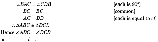
i.e. the angle of incidence is equal to the angle of reflection. The proves the first law of reflection.
Further, since the incident ray SB, the normal BN and the reflected ray BD are respectively perpendicular to the incident wave front AB, the reflecting surface XY and the reflected wave front CD (all of which are perpendicular to the plane of the paper) therefore, they all lie in the plane of the paper i.e. in the same plane. This proves the second law of reflection.
13. Law of refraction on this basis of Huygens’ wave theory Consider a plane wavefront AB incident on a plane surface XY, separating two media 1 and 2, as shown in Figure.
Let v1 and v2 be the velocities of light in two media, with v1 <v2.
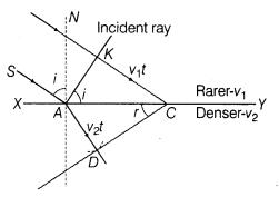
The wave front first strikes at point A and then at the successive points towards C. According to Huygens’ principle, from each point on AC, the secondary wavelets starts growing in the second medium with speed v2. Let the disturbance take time t to travel from B to C, then BC = v1t. During the time the disturbance from B reaches the point C, the secondary wavelets from point A must have spread over a hemisphere of radius AD = v2t in the second medium. The tangent plane CD drawn from point C over this hemisphere of radius v2t will be the new refracted wave front.
Let the angles of incidence and refraction be i and r, respectively.
From right AABC, we have
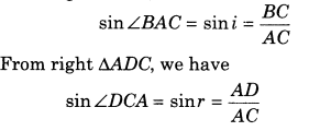

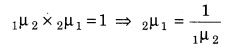
This proves Snell’s law of refraction. The constant 1μ2 is called the refractive index of the socond medium with respect to first medium.
Further, since the incident ray SA, the normal AN and the refracted ray AD are respectively perpendicular to the indicent wave front AB, the dividing surface XY and the refracted wave front CD (all perpendicular to the plane of the paper), therefore, they all lie in the plane of the paper, i.e. in the same plane. This proves another law of refraction.
Leave a Reply